Create definition file
Not every combination of VKB modules has a pre-made definition file available. To enable support for LED outputs and friendly names in such a configuration, it is necessary to create a new definition file.
To help with the creation of such files, the VKB/MobiFlight Definer tool can build a file for the default configuration of most controller combinations:
Startup
Ensure that your VKB controller is connected and MobiFlight is not running.
Download, extract and run the latest release of the definer tool from the link above.
Select controller

Select your VKB controller from the list of controllers shown by entering the number of the list entry and pressing the enter key.
Select the base
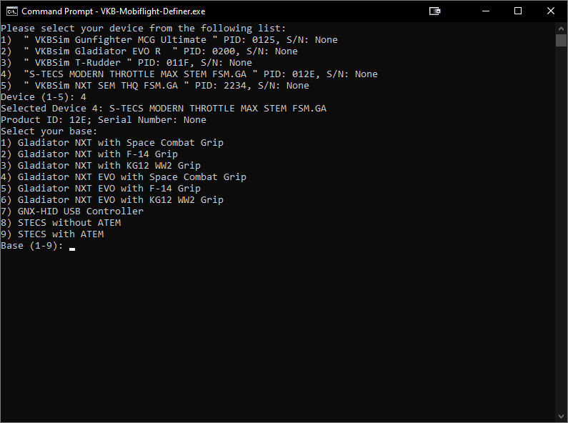
Select your base from the list by typing the corresponding number and pressing enter.
Some bases may contain extension modules like grips or the ATEM. That is because these modules affect the button mapping on the base or act as a part of the base.
If your controller is a GNX throttle combo, the base unit is the GNX-HID USB Controller.
Select add-on modules
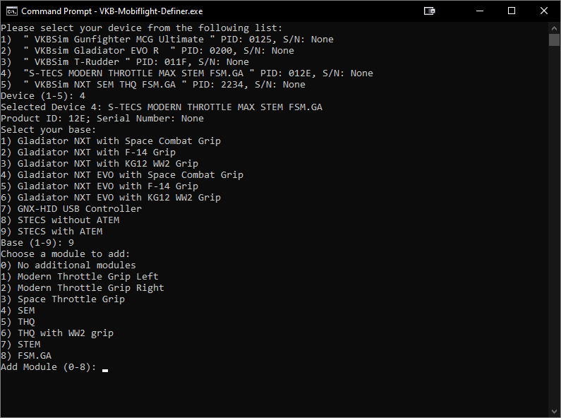
Select each extension module that is part of your controller. If you have multiples of the same module, add the same module type multiple times.
It is generally recommended to follow the order in this list:
- Grips
- SEM
- THQ
- STEM
- FSM.GA
For STECS split throttle grips, choose the left grip first. If one of your THQs has a WW2 throttle grip, choose that one last. There is no distinction between SEM and SEM-V, or between THQ and THQ-V.
Once all modules have been added, select 0 and proceed with step 9, Enable encoder API.
Select grip preset
This step is for the STECS MTG-R. For other modules, skip to step 7, Enter first button ID.
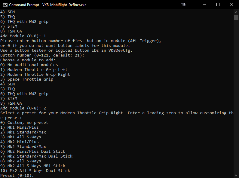
Since the STECS MTG-R allows for swappable button modules, this menu allows you to choose the button modules installed in your grip. Common grip configurations are prepared as presets, but you can also choose a fully custom preset by typing in 0.
Tip
You can base a custom configuration off an existing preset by entering the number with a leading zero, e.g. 05.
Select button modules
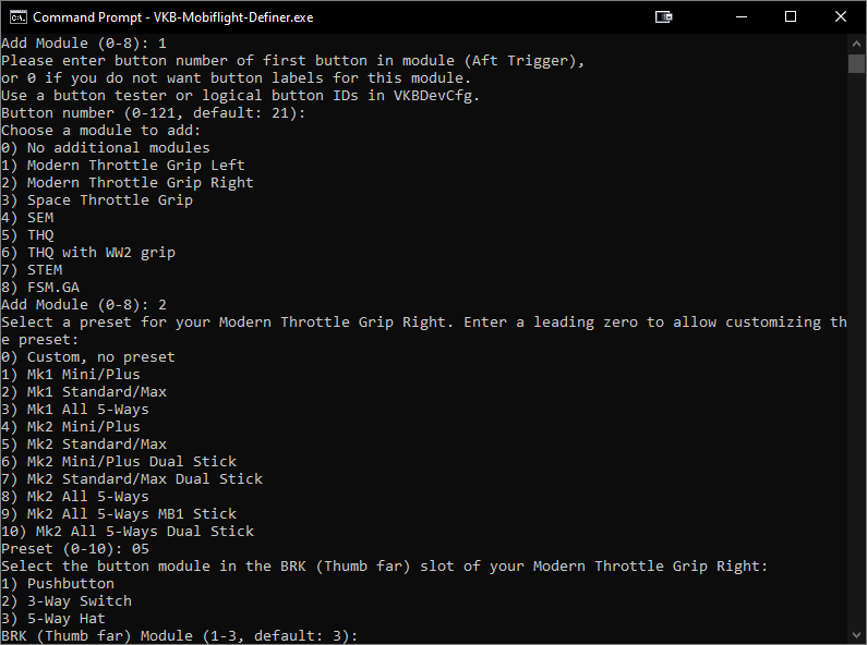
If you selected a custom preset, you will be prompted which button modules are installed in each slot. Enter the number in the list and continue. The list will change between button module slots to reflect the valid button modules for each slot.
Repeat this step until all button module slots are filled.
Enter first button ID
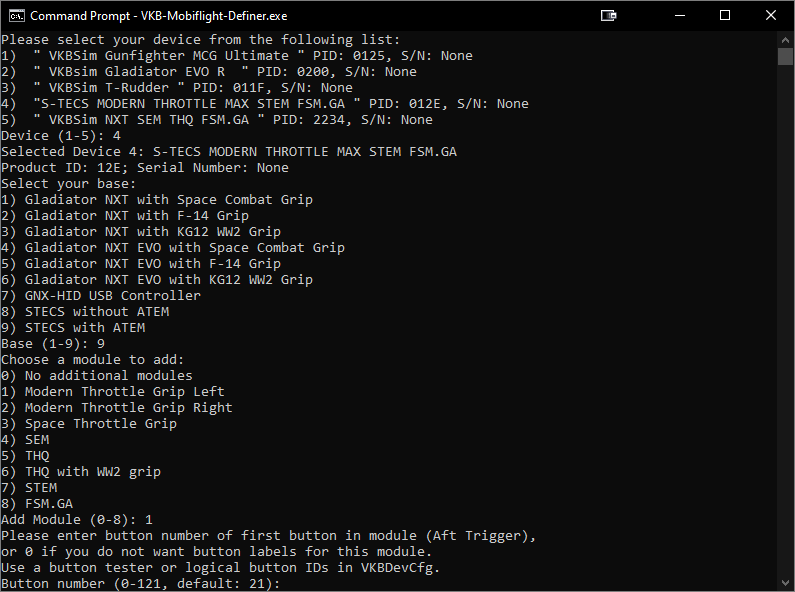
Enter the ID of the first button of the current extension module. A label to find that button is shown in the prompt.
If you are following the controller order mentioned in step 4, Select add-on modules, the default is usually correct, but you can always verify in a button tester application.
Enter first LED ID
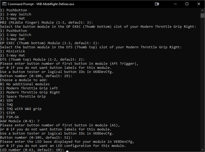
Enter the base LED ID of the first module. It can be looked up in the VKBDevCfg external controller tab.
If you are following the controller order mentioned in step 4, Select add-on modules, the default is usually correct.
Return to step 4, Select add-on modules to continue setting up further modules.
Enable encoder API
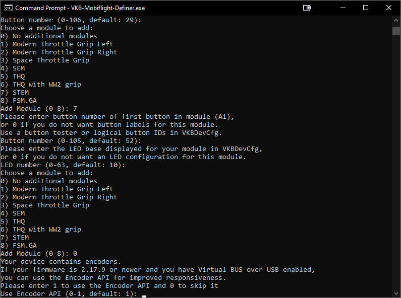
If any of your controller components feature rotary encoders, you will be asked to enable the rotary encoder API. This is required for the advanced encoder feature and generally does not come with drawbacks. It is recommended to accept this.
Enter encoder IDs
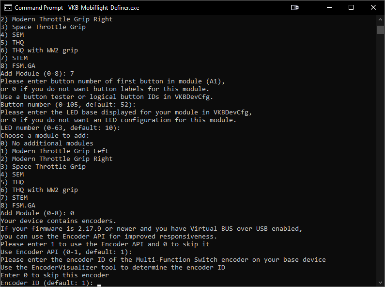
Enter the ID of the encoder described in the prompt.
If you are following the controller order mentioned in step 4, Select add-on modules, the default is usually correct.
When in doubt (perhaps because you have added shift states to encoders in VKBDevCfg), an encoder visualizer application is available to test which encoder ID represents which encoder. Complete this step until all encoders are assigned an ID.
Copy file
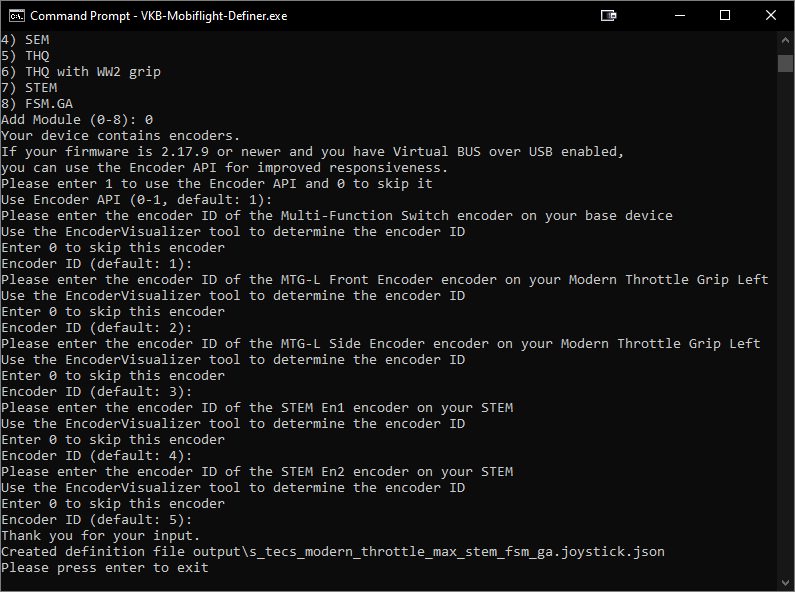
The utility will inform you that the file has been created. You can find it in the output folder of the definer application.
Note
While this definition file will be suitable for automatically configured VKB devices, some configuration edits, like changing logical button IDs, may require manual edits to the definition file.
Copy the file to the Joysticks folder in your MobiFlight installation directory.
Tip
If you used the MobiFlight Setup from the MobiFlight website, you can find the destination folder by entering %LOCALAPPDATA%\MobiFlight\MobiFlight Connector\Joysticks into the address bar.